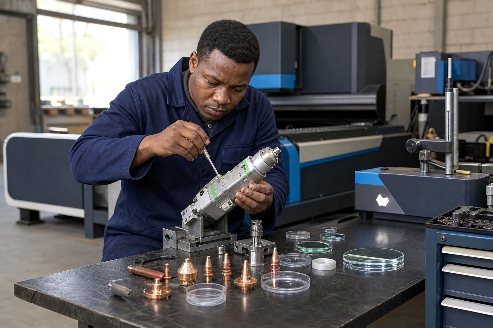

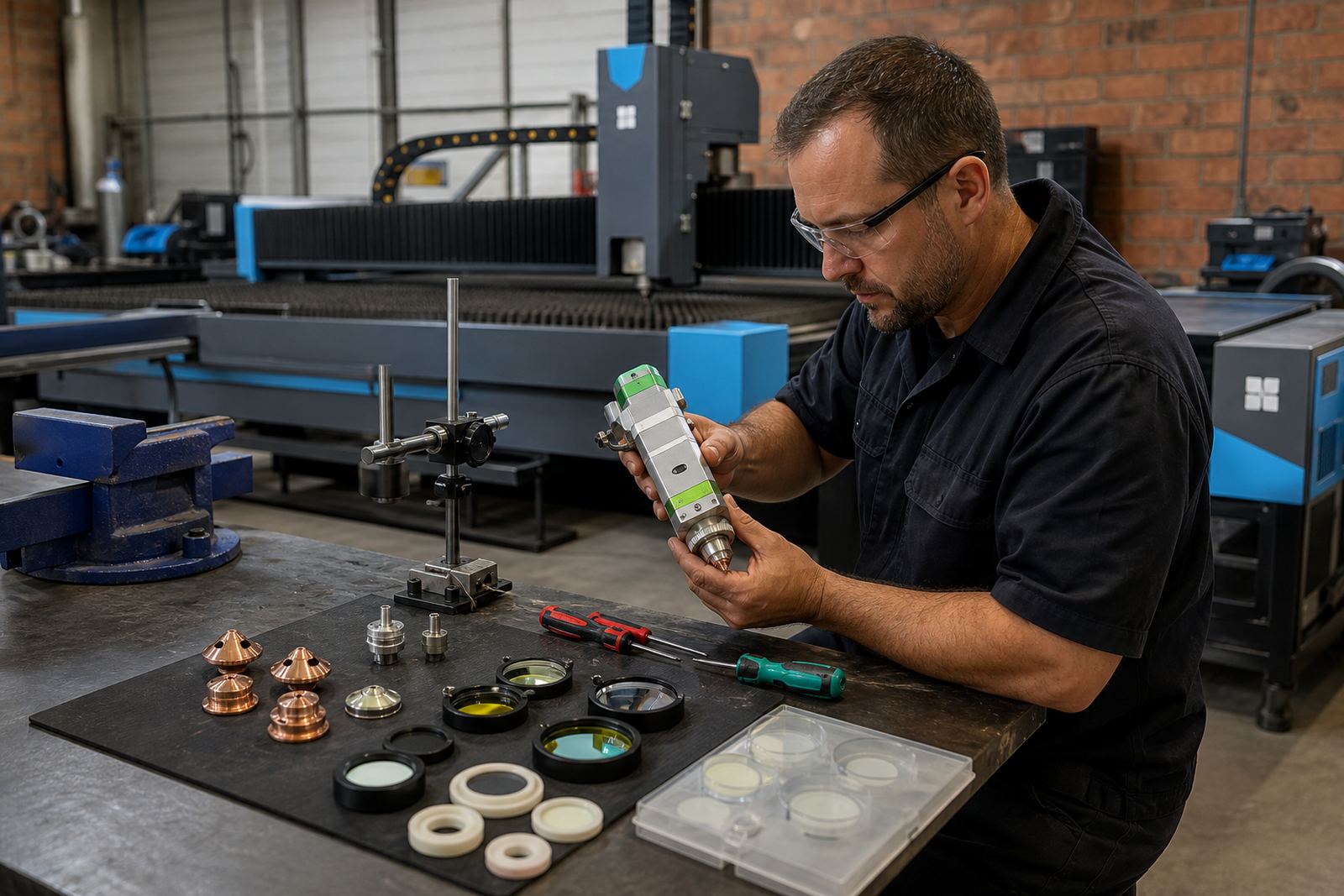
Start with the part that sits closest to the cut
The nozzle is usually the first part to inspect because it sits nearest to the sheet and gets the hardest wear. A single layer nozzle has one opening profile, while a double layer nozzle has a stepped internal form that helps shape assist gas flow. If the cut edge shows dross, taper or an uneven kerf, the nozzle may be burnt, oval or blocked with fine spatter.
Look at the tip under good light and turn it by hand if it is loose enough to remove. A clean nozzle opening should look centred, round and free of burrs. If the hole is nicked, the body is bent or the copper surface has dark rings, the nozzle should be checked against the cut quality before more sheet goes through the machine.
- Single layer nozzles suit straightforward gas delivery.
- Double layer nozzles are built with a stepped interior.
- Damage near the orifice changes the gas stream fast.
- Carbon marks often point to heat or spatter contact.
Reading the lens stack in the head
A cutting head normally carries a focus lens and a collimator lens, and the two do different jobs. The collimator lens straightens the incoming beam, while the focus lens brings it down to the required spot size at the sheet. If one lens is dirty, scratched or seated badly, the cut may wander, lose edge quality or produce extra heat in the kerf.
When identifying lens position, work from the beam path, not from guesswork. The collimator sits higher in the optical path and the focus lens sits lower, closer to the nozzle assembly. A mistaken swap can create poor cut results even when the lenses still look clear to the eye.
- Use clean gloves when handling optical parts.
- Check for haze, pitting or a slight milky patch.
- Confirm the lens sits flat in its holder.
- Do not force a lens that resists seating.
Protective windows and why the format matters
The protective window shields the more expensive optics from dust, smoke and splash-back. It is usually the easiest window to identify because it sits in a carrier close to the lower part of the head, and it may show heat tint or a fine dust ring before the lens above it does. Once the window is marked, the beam may scatter and the head can start behaving as if the focus has drifted.
Window format matters because thickness, diameter and edge finish have to match the head body and the clamping seat. A chipped edge can crack under pressure, while a window fitted upside down or with the wrong face position can show unusual marks after a short run. On busy sheet-metal floors, that kind of mix-up is common after a rushed changeover.
- Cloudy patches usually mean contamination or heat stress.
- Small edge chips can spread under clamp pressure.
- Fingerprints often show as pale circular marks.
- A correct carrier should sit square in the head.
Ceramic rings, seals and the lower end of the head
The ceramic ring sits near the nozzle area and helps keep the lower end of the head stable and insulated. It also supports the geometry around the nozzle and sensor area. If it is cracked, glazed or chipped, the nozzle may sit off-centre and the cut can start drifting even when the lens stack looks fine.
Head seals matter too. A damaged seal lets dust and gas leakage build inside the head, which can mark the window and the lens holder. When we inspect a head, we look for loose rings, heat discolouration, and fine powder around the seat because those signs usually point to handling damage or a previous collision.
- Cracks in ceramic often hide until the ring is removed.
- Glazing can indicate repeated heat exposure.
- Loose seating changes the nozzle height line.
- Seal wear often leaves dust at the joint.
Capacitive sensing and focus setting clues
Many fibre laser heads use capacitive height sensing to hold the stand-off between nozzle and sheet. If the sensor reading is unstable, the cut may start too high or too low and the edge quality will change from one area of the sheet to another. That fault is often mistaken for a nozzle problem, but the sensor, cabling or mounting can be the real issue.
Focus setting should also be checked against the material type and thickness being cut. Mild steel, stainless steel and aluminium each react differently, and a head set too high or too low can leave a wide kerf, excessive burr or heat stain. A proper part identification check therefore includes the sensor face, the focus position and the condition of the lower optics.
- Erratic height control can mimic lens damage.
- Focus drift shows up as changing edge texture.
- Sensor dirt gives false readings on some jobs.
- Wrong focus often shows before the part fails completely.
A practical check before bench service or on-site alignment
If the head is already off the machine, lay the parts out in sequence and keep each item clean and separate. Start with the nozzle, then check the ceramic ring, lower holder, protective window and lens seats. That order helps you spot wear where the beam path narrows and where contamination usually builds first.
When the head remains on site, we check the visible tip, the sensor behaviour, gas path condition and any crash marks around the body. Clear part identification saves time when a sheet-metal shop in Johannesburg or Durban needs a precise rebuild, not a random parts swap. It also helps when preparing spare heads for work across Pretoria, Cape Town, Rustenburg and the East Rand.
- Photograph each part before removal.
- Keep damaged items beside clean spares for comparison.
- Note any heat marks, chips or oval wear.
- Record the head body number if visible.