
What the sensor is measuring at the nozzle
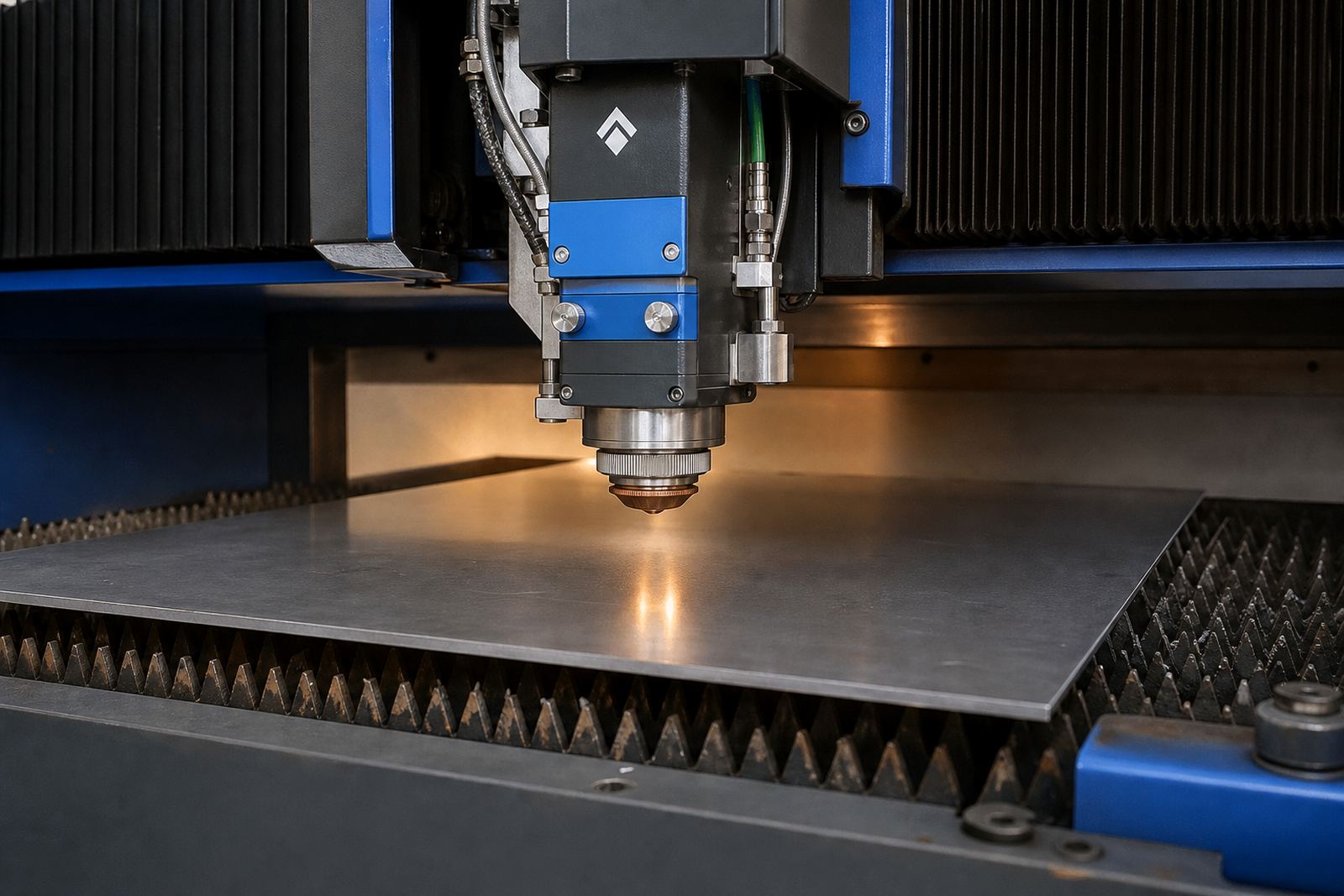
Capacitive height sensing works by sending a small field toward the sheet, then measuring how that field changes as the nozzle-to-plate distance shifts. The control system uses that reading to hold the head at the set cutting height while the table moves over the job.
For sheet-metal work, that gap is not guesswork. Mild steel, stainless steel and aluminium each behave differently under heat, gas flow and surface condition. Rust, scale and oily film can affect the signal, so the system must be set up with clean parts and a sound earthing path. If the signal is unstable, the head can hover too high, dip too low, or hunt up and down on corners and thin plate.
In practice, the sensor is part of the cutting chain, not a separate accessory. Nozzle condition, protective window cleanliness, focus position and ceramic ring condition all influence what the height control sees. When a shop in Spartan or on the East Rand reports inconsistent cut height, the first check is often not the software. It is the hardware path at the head.
The parts that shape a clean height reading
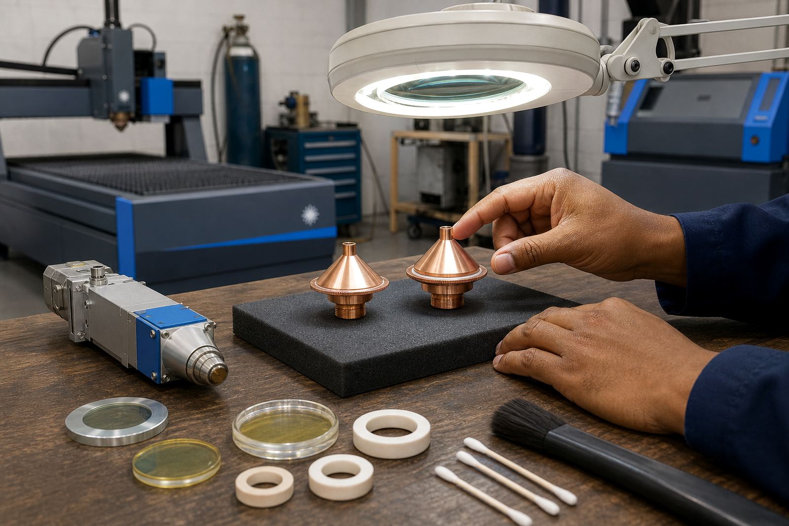
The sensing circuit depends on a few small parts working together. A bent nozzle, carbon on the tip, a cracked ceramic ring or dust on the protective window can distort the reading. Even if the machine still cuts, the control may start chasing the surface instead of holding a steady gap.
- Single layer and double layer nozzles need the correct bore and clean edges.
- Focus lenses and collimator lenses must stay clean and seated correctly.
- Protective windows should be checked for haze, spatter and pinholes.
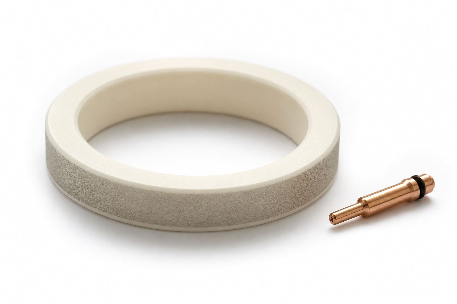
- Ceramic rings must not carry burn marks, chips or tracking lines.
- The head seal and gas path should stay free of fine metal dust.
A careful cleaning routine matters more than a quick wipe with the first cloth nearby. Use clean, lint free handling, inspect under good light and replace parts that have taken heat or impact. On a busy shop floor, a small mark can travel through several shifts before someone notices the cut quality slipping.
How focus and height work together during cutting
Height sensing does not work in isolation from focus. The focus setting determines where the beam waist sits in relation to the sheet, while the capacitive system keeps the nozzle at the programmed gap. If the focus is off, the cut may show dross, poor bevel control or a wide kerf even when the height looks correct.
That is why a focus setting check forms part of sensible maintenance. A technician will confirm the cut height, inspect the nozzle centring and review the lens stack before changing settings in the controller. If the machine has recently had a small crash, the head may still move, but the beam path can shift enough to throw off the sensor reading and the pierce result.
For most sheet-metal shops, the warning signs are plain. The torch starts to leave a rougher top edge, corners burn more than straight runs, and pierces throw more spatter than usual. Those symptoms can point to gas, focus or height sensing, sometimes all three on the same job.
Fault signs that point to a sensing problem
A capacitive sensing fault does not always stop the machine. More often, it shows up as drift, chatter or inconsistent quality across the sheet. The operator may see the head lifting and dipping without a clear reason, or the controller may refuse to settle at the set height on certain materials.
Common signs include noisy following on thin plate, rough starts on pierce points, corner marks where the head hesitated, and repeated height alarms on clean material. If the issue appears after a nozzle change or lens service, the problem may be a part seated slightly off centre. If it appears after a collision, the ceramic ring, sensor body or mounting may need closer inspection.
- Check whether the nozzle tip is true and undamaged.
- Confirm that the protective window is seated and clean.
- Inspect the ceramic ring for cracks, heat marks and loose fit.
- Look for metal dust in the gas path and around the sensor area.
- Test the height reading on a known good sheet before chasing software settings.
A bench check tells more than a rushed site guess
When a head comes in for bench service, the sensing circuit can be checked in a calm, repeatable way. That makes it easier to separate a dirty optical stack from a damaged sensor body or a poor electrical path. Bench work also allows a proper look at head seals, lens seats and the nozzle seat without the pressure of a live production queue.
On-site alignment still has its place, especially when a machine in Johannesburg, Pretoria, Durban, Cape Town or Rustenburg is cutting but not cutting well enough for the job. Field work is useful for head alignment after a crash, or when the sensor reads differently across the bed and the machine needs a practical correction where it sits.
A sensible maintenance visit usually starts with the head, not the table. If the signal path is sound, the head sits square and the lens stack is clean, the rest of the job becomes far easier to interpret.
A local sheet-metal example from a busy spindle day
A shop in the East Rand was cutting mixed orders in stainless and mild steel when the operator began seeing uneven pierces on one side of the nest. The nozzle had been changed twice, the cutting gas looked fine and the software settings were left alone. The problem turned out to be a tired ceramic ring with fine tracking marks and a protective window that had started to haze at the edge.
Once those parts were replaced and the head was checked for centre and focus, the height reading settled again. The machine was not facing a dramatic failure, just a chain of small faults that added up. That is typical with capacitive sensing. It reacts to the condition of the whole head, not just one obvious part.
For busy fabricators, the lesson is straightforward. Keep the nozzle clean, watch the lens stack, and treat small heat marks as useful warnings rather than cosmetic flaws. A head that senses properly is easier to tune, easier to trust on thin sheet and less likely to waste material when the cut path gets tight.
What a careful maintenance routine usually includes
Capacitive height sensing lasts longer when the rest of the head stays in good order. That means regular inspection, proper handling and a record of what changed after any crash, nozzle swap or lens service. It also means not mixing worn parts with fresh ones and expecting the machine to sort out the difference on its own.
- Clean the nozzle seat and inspect the tip under light.
- Check protective windows for spatter and edge haze.
- Confirm lens cleanliness before refitting the stack.
- Look at ceramic rings for burn trails or chips.
- Run a height check on a known sheet after service.
For shops that cut every day, that routine saves time in the long run. It keeps the sensing stable, the cuts more predictable and the head easier to service when the machine starts showing signs of wear.